


CGPACK > JAN-2015
15-JAN-2015: ParaFEM/CGPACK hybrid model results.
ParaFEM is an MPI FE library with proven excellent scaling on Tier-1 and Tier-0 systems. By linking ParaFEM and CGPACK and generic flexible open and expandable FE/CA hybrid model is obtained.
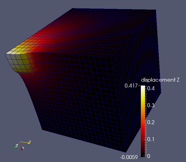
The FE models is a 10mm by 10mm by 10mm cube of steel with typical properties: Young's modulus is 200GPa and the Poisson's ratio is 0.33. The model is taken from Program 12.1 from Lee Margett's Chapter 12 of the book "Programming the Finite Element Method", 5th Edition. The BC are u1(x1=0)=0, u2(x2=0)=0, u3(x3=0)=0. The tensile load is applied along x3 at x3=10mm. The load is distributed along a small patch around x1=x2=0. The load is increased in 5 load increments from 0 to 1kN.
Polycrystalline microstructure is populated in the whole model. There are 1000 grains, i.e. the mean grain size is 1mm. The mean grain size is deliberately taken much higher than in a typical mild steel, to speed up the calculations in this proof of concept example. The grain resolution is 10,000, meaning that each grain is represented, on average, by 10,000 cellular automata cells.
The fracture length scale is the length a cleavage crack will propagate per unit of time. In other words the fracture length is equivalent to the cleavage speed. In this example it is taken as 1 km/s. As this is a quasi-static model, there are no time increments. Artificial time increments are linked to the load increments, as:
! no real time increments in this problem, so use the inverse
! of the number of load iterations.
cgca_time_inc = 1.0_rdef / cgca_linum * 1.0e-4

! run cleavage for a correct number of iterations, which is a function
! of the characteristic length and the time increment
cgca_clvg_iter = nint( cgca_length * cgca_lres * cgca_time_inc )
Below is the contour plot of u3, produced by FE.
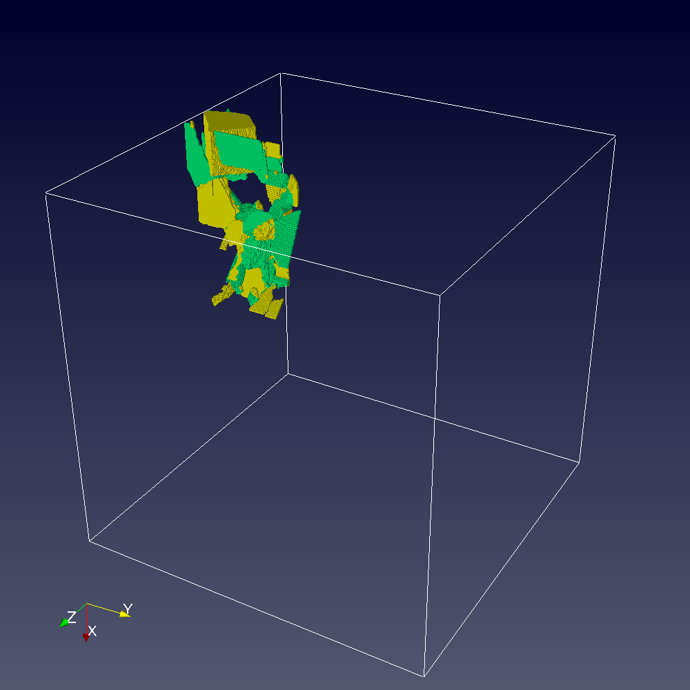
A single microcrack, which acts as the cleavage nucleus, was positioned at x1=x2=0, x3=5mm.
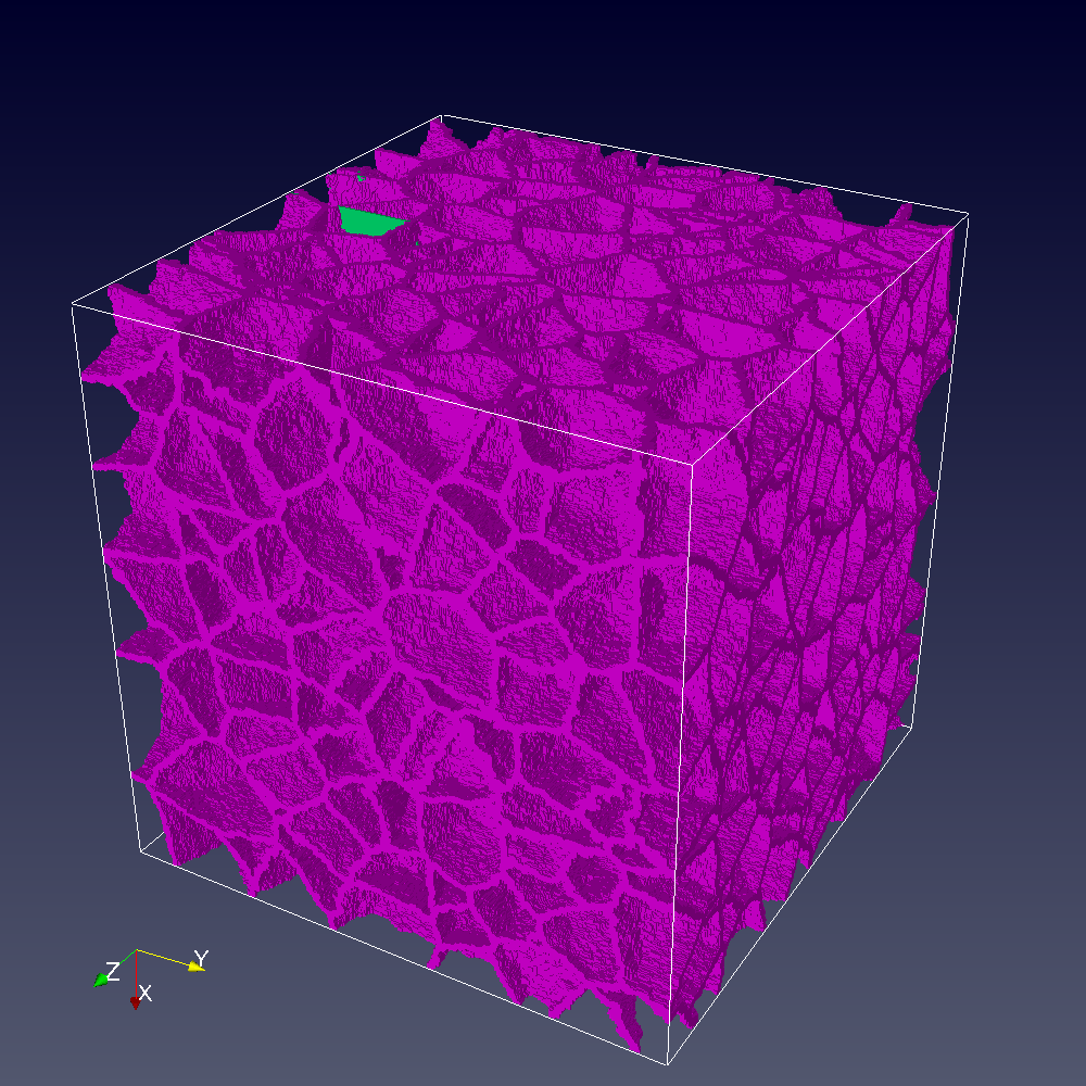
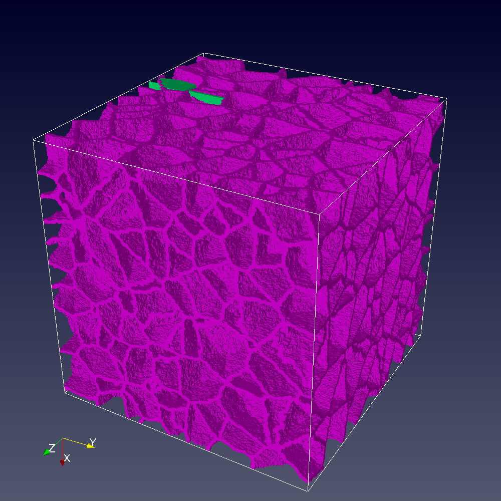
Results from two runs of the same model are shown below. The microstructure is randomly generated each time, so it's unique for each run. Note the variability in the crack size and path.
Grain boundaries:
|
|
Cracks, green are on {110} planes, yellow are on {100} planes:
|

|
Cracks superimposed over semi-transparent grain boundaries.
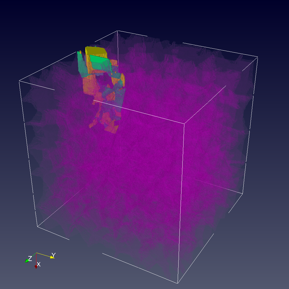
|
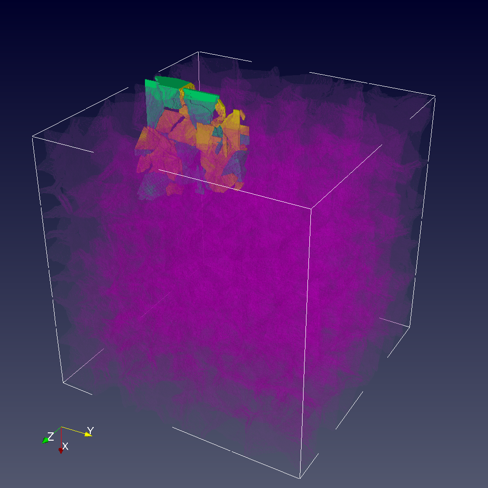
|