

CGPACK > MAY-2013
3-MAY-2013: Trans-granular cleavage.
The basic transgranular cleavage routines are written, but need extensive testing. Below is a single cleavage propagation increment. There is a single grain in the model with its rotation tensor being the unit tensor. The cleavage nucleus is at (5,5,5)[1,1,1]. The max. principal stress vector is (1,0,0). One can see that 8 neighbouring cells cleaved on (100) plane.
7-MAY-2013: Trans-granular cleavage with self-similar boundary conditions.
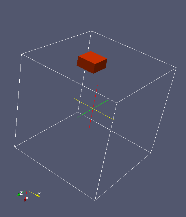
The model is a single grain, aligned with the spatial (cellular) coord. system. The array is (10,10,10)[2,2,2]. The max. principal stress vector is (1,1,0). Hence the cleavage on a {110} plane.
8-MAY-2013: A larger cleavage example.
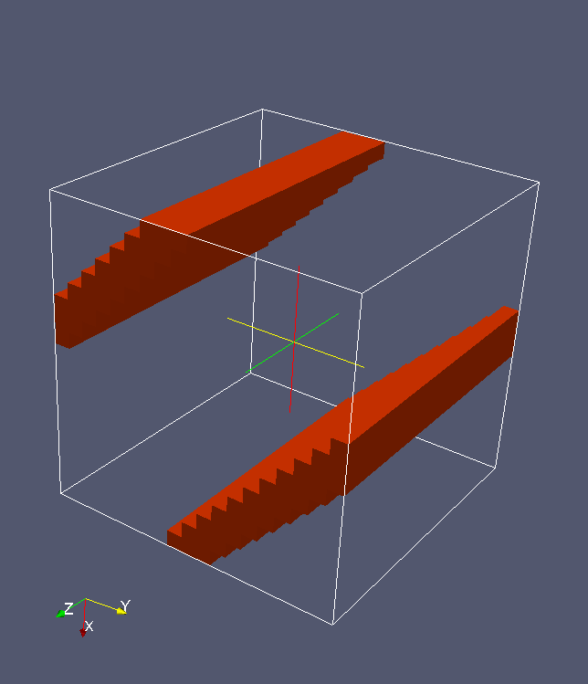
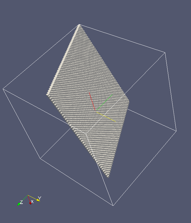
The array is (50,50,50)[2,2,2], single grain with random orientation. The cleavage plane is of {100} family. This is the crack after 60 cleavage increments.
9-MAY-2013: Problems with deterministic cleavage propagation with 26-cell 3D neighbourhood.
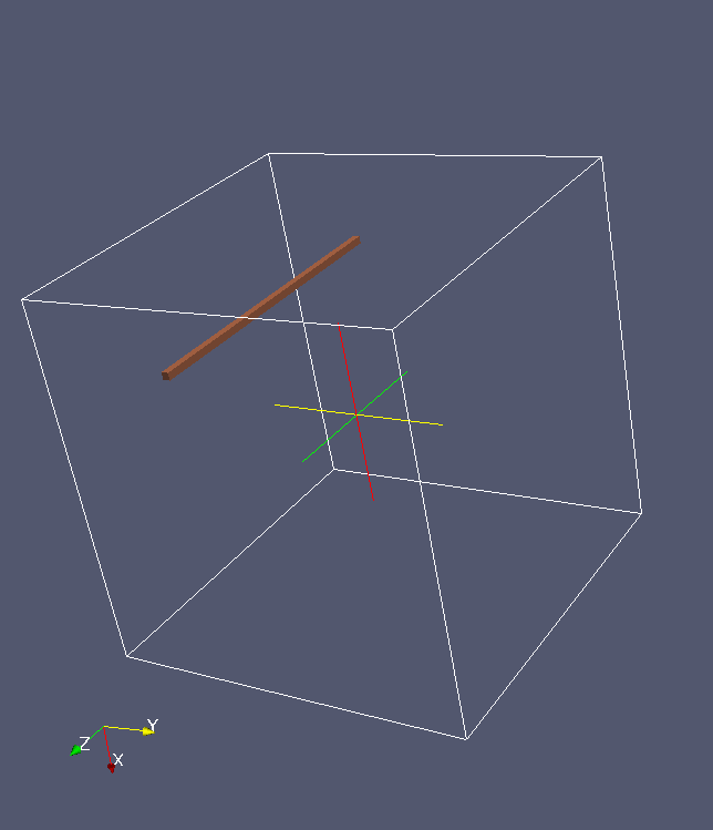
A massive problem of 26-cell 3D neighbourhood is that there are 3 different angles between the neighbouring unit vectors from the central cell to a neighbouring cell, see Shterenlikht A, Resolving a randomly oriented cleavage plane within there-dimensional cellular automata model, Discrete and Computational Geometry, submitted, April 2013. This makes the resolution of a cleavage (or any other) plane into cells very hard. Depending on the orientation, the plane might resolve into 8, 6, 4 or 2 cells. While the values of 8, 6 and 4 are more or less acceptable, because they create a plane that can grow, the 2 cell plane is clearly not a plane, but a line. It can only grow as a line. This representation of a crack is unrealistic.
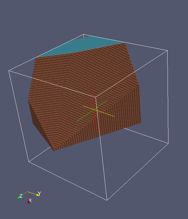
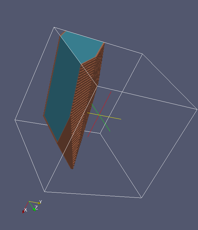
On the other hand, if one wants to relax the conditions under which a cell is considered to belong to the cleavage plane, then some cleavage plane orientations will incude cells lying on more than one plane, and these grow as 3D bodies. Again, this representation of cracks is unsatisfactory.
The solution might lie in using a probabilistic, rather than a deterministic criterion. This is going to be explored next.
The two images below illustrate a situation with relaxed plane resolution condition, resulting in a crack that is a vast 3D body.
This image shows an example of a linear 1D crack:
13-MAY-2013: Distinguishing crack edges from crack flanks.
It seems it is necessary to distinguish between crack edges, which are "active" parts of a crack, and crack flanks, which are "inactive". Crack edges can attract new cells, and thus a crack can grow. Crack flanks cannot attract new cells. Thus crack growth can be promoted only on the requried planes, and stopped along other directions.
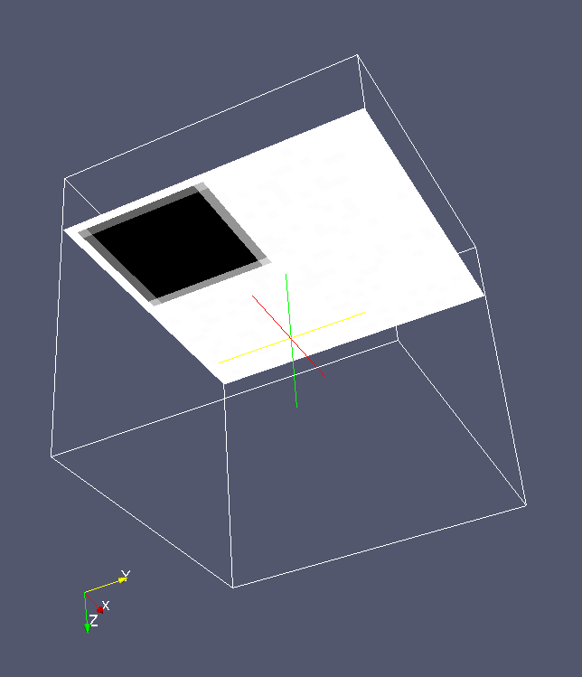
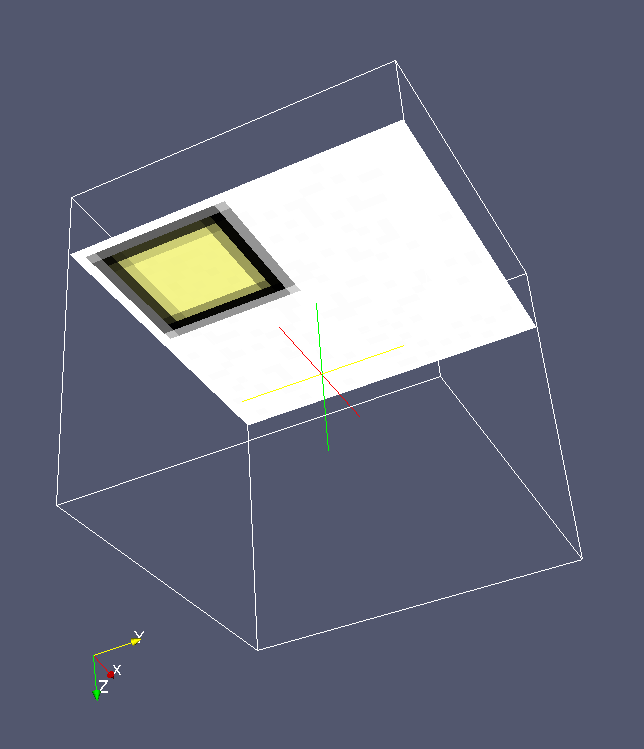
In this example, a cluster of cells are given an edge state (black). Then a crack flank deactivation routine marks all interior cells, i.e. cleaved cells with 8 cleaved neighbours or more, as inactive (yellow).
